Software: Hosonsoft | Scope: Physical head alignment only (no digital offsets)
Purpose
Verify and correct the printhead’s physical vertical alignment so all channels stitch straight with no left/right “splice” offset before any digital fine-tuning.
Prerequisites
-
Head mechanically installed and inked; no leaks; carriage moves freely
-
Nozzle test acceptable (≥95% firing)
-
Media: DTF film loaded; standard print mode (settings you usually use ie. Eclosion settings (Mode, Type), Print Speed (High), Print Direction (bidi)
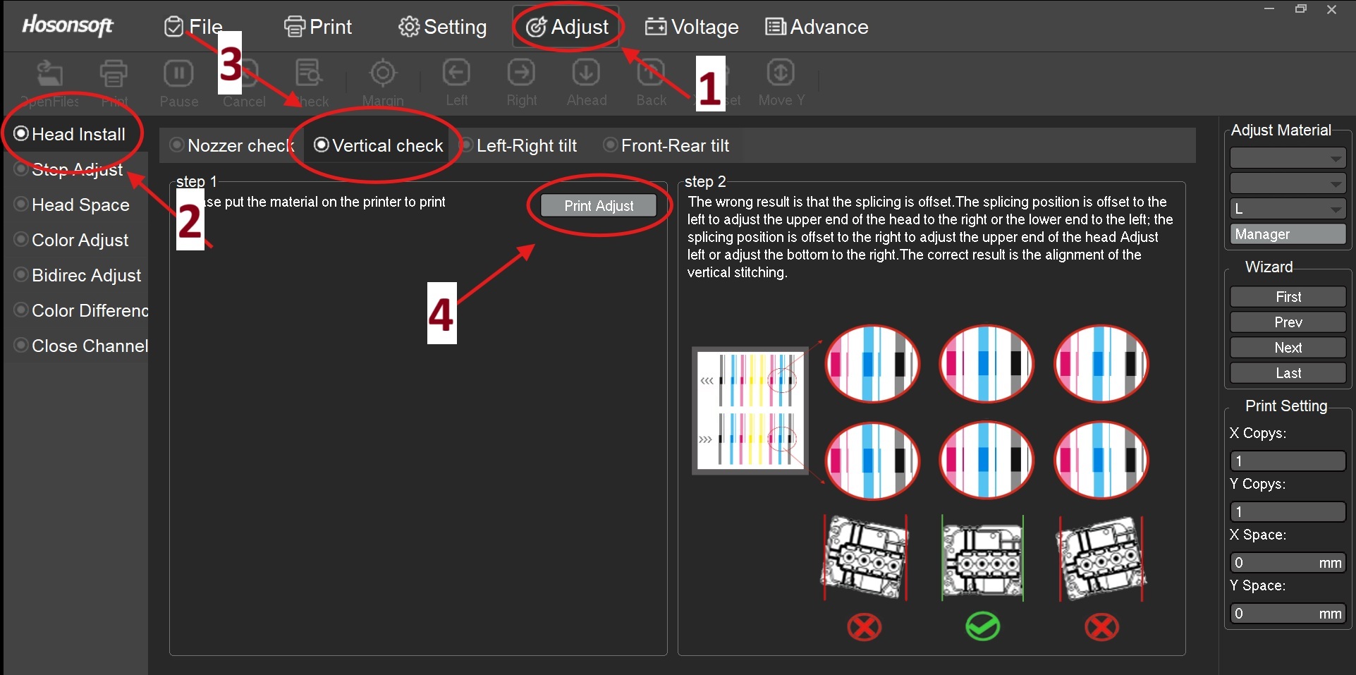
Navigation (refer to image callouts)
-
Adjust tab (top menu) — [Callout 1]
-
Head Install (left panel) — [Callout 2]
-
Vertical check (tab header) — [Callout 3]
-
Click Print Adjust to print the chart — [Callout 4]
Step-by-Step
1. Prepare media & carriage
-
-
in Control Software (Hosonsoft / PrintEXP) Go to Adjust → Head Install → Vertical check, press Print Adjust (Printer prints Calibration Chart).
-
Let the chart complete; do not move media between iterations.
-
2. Print the Vertical Check chart
-
In Adjust → Head Install → Vertical check, press Print Adjust.
-
Let the chart complete; do not move media between iterations.
3. Read Test Chart (diagnosis)
- Inspect each channel’s vertical bars.
- Correct pattern: Bars align in a straight, continuous column (see right portion of photo below labeled as step 2 for example of correctly aligned head pattern).
- Incorrect pattern (left splice): Bars step to the left at the join. (See right portion of photo below labeled as step 2)
- Incorrect pattern (right splice): Bars step to the right at the join.
(See right portion of photo below labeled as step 2)
4. Adjust incorrect calibration pattern:
Slightly loosen the upper and two lower head-mount screws just enough to allow micro-movement. Support the head; do not stress FFCs/ink lines.
- If splice steps left → nudge the upper end right or lower end left.
- If splice steps right → nudge the upper end left or lower end right.
- Movements should be sub-millimetric. Use the mount as a pivot; keep head face parallel to the carriage rail.
5. Lock-down sequence
-
Lightly snug upper screws, then lower; re-torque in cross pattern.
6. Re-print & verify
-
re-print pattern using Print Adjust button in control panel
- Repeat Steps 2–6 until all channels show straight, unstepped vertical stitching.
7. Final acceptance
- No visible step at splice under 10× magnification.
- No new banding on a 50–100 mm solid fill test.
-
Proceed to Bidirectional and Step/Color digital adjustments.
Notes & Tolerances
-
Typical acceptable splice error: ≤0.05–0.10 mm (visually seamless).
-
Always adjust physically first, then apply digital offsets only if residual error remains.
Common Mistakes
-
Over-tightening one side first → introduces tilt; always cross-torque.
-
Compensating a mechanical mis-seat with digital offsets → inconsistent results across swaths.
-
Skipping nozzle check prior to alignment → misreads caused by clogged nozzles.
Troubleshooting
-
Error persists directionally: Check for debris under head feet or uneven bracket. Reseat head.
-
Pattern changes across width: Inspect carriage rail and encoder strip for contamination or looseness.
-
Random mis-stitching: Verify platen vacuum/film flatness; check head cable seating.
Next Steps (after pass)
-
Run Bidirec Adjust, then Step Adjust, then Color Adjust ect... in Hosonsoft.
-
Save a dated Baseline Alignment Record (photo of chart + notes)